
Visual reference for the industrial process environment. Final fan configuration is selected from the actual operating conditions.


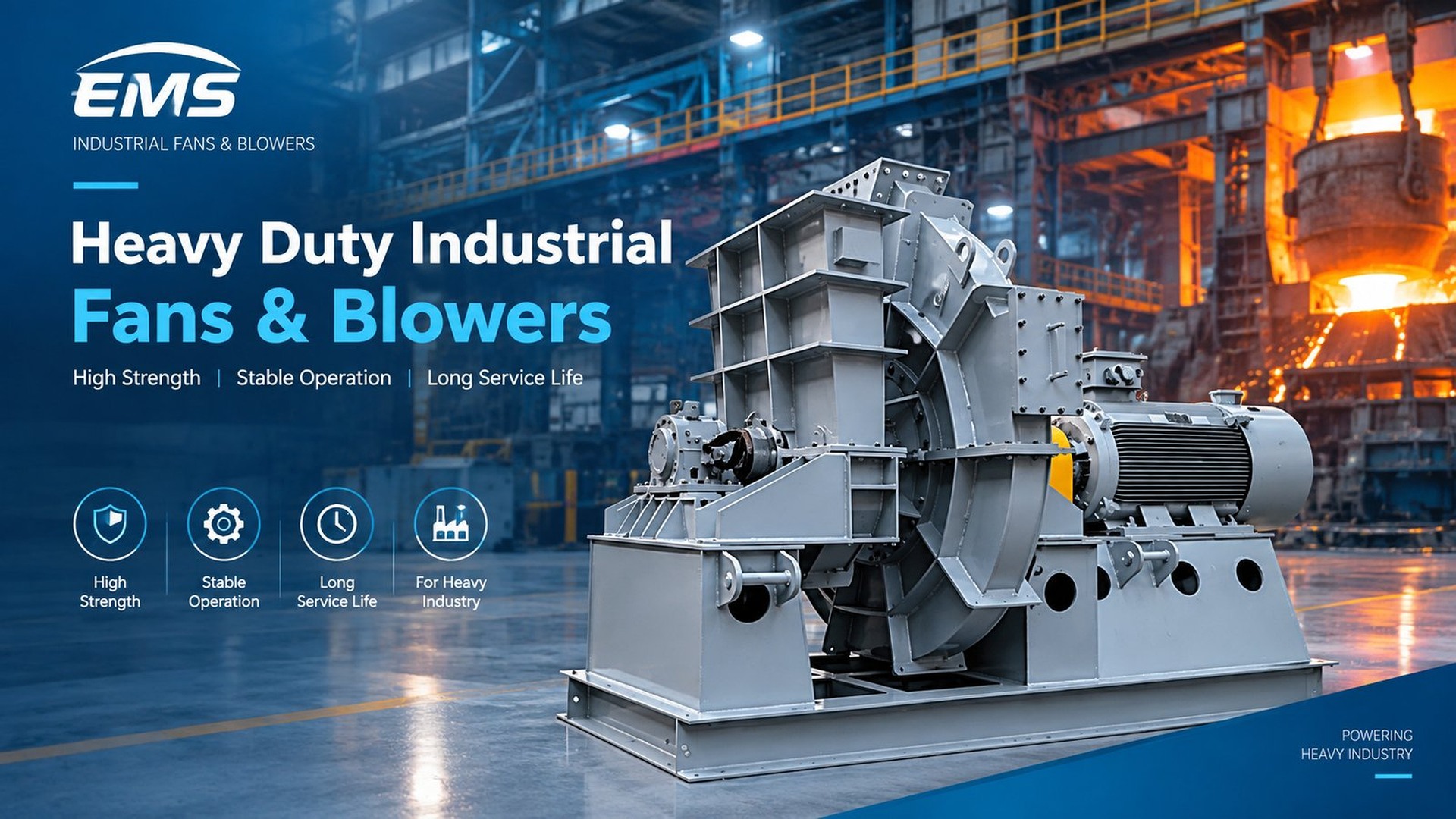
Engineering fan solution for cement industry applications, selected according to airflow, pressure, temperature, medium and installation conditions.
Explore Raw Mill Fan engineering selection →Request a Quote →Engineering fan solution for cement industry applications, selected according to airflow, pressure, temperature, medium and installation conditions.
Explore Cement Mill Fan engineering selection →Request a Quote →Engineering fan solution for cement industry applications, selected according to airflow, pressure, temperature, medium and installation conditions.
Explore Mill Circulation Fan engineering selection →Request a Quote →Explore the operating principle for Raw & Cement Mill Fans. Follow the air or gas through a representative system.
Conceptual flow path:
An interactive 3D view is available with JavaScript and WebGL. The sequence above remains available without them.
Air or gas reaches the upstream side of the selected fan system.
Conceptual 3D illustration · not product CAD or operating footage. Fan geometry, impeller, drive arrangement, dimensions and motion are generic teaching examples, not verified construction or performance of the named product. Flow timing, fan symbol and dimensions are illustrative, not equipment performance data or a project layout. General airflow principle only. This page does not establish a specific supply, exhaust or recirculation arrangement.
Explore related fan applications within this industry to compare operating duties and suitable fan configurations.
Share your operating conditions on our dedicated inquiry page. Our engineering team will review your application, performance requirements and configuration.
Request a Quote →